http://circuitrydesigner.blogspot.com.ng/p/smps_3.html
- Home
- Circuits Category
- Videos & Images
- Circuit Diagrams
- Contact us
- About
circuitrydesigner.blogspot.com

Learn how to make new electronic circuit designs, circuit modifications, circuit analysis enquiries and lot more about circuits.Are you a student of Electrical Electronics Engineering? This is the right place for you to harness your potentials every were. For more information, contact me!
Green LED
Yellow LED
Red LED
Blue LED
Sunday, 7 February 2016
Simplest bistable multivibrator circuit
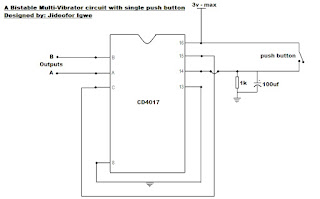
A BistableMultiVibrator is a circuit with two states which can maintain a "high" or "low" logic at the presence of power. When triggered with a pulse, it flips state from its initial condition to the next state. This type of circuit can be built by bjts, resistors and capacitors, requiring a thorough circuit know-how to implement, including the addition of cost of components and calculations in optimizing the circuit behaviour.
Such circuit can equally be implemented with the versatile chip; CD4017 and just a resistor and a capacitor as can be witnessed in the diagram.
When powered, the IC maintains a "high" logic at the output "A" once you push the switch, it will change the state of output "A" to "low" logic and then transfers the "high" logic to output "B". This change in position is usually augmented when ever pin 14 of the IC is raised to Vcc.
The capacitor and the resistor formed an RC resonant tank which prevents unwanted fast transition between states when triggered with an uneven pulse at the switch which may be caused by low conductance of the switch. It equally pulls down the input pin(pin14) to ground so as to prevent the interference of stray signals within its environment by absorbing it before the IC picks it up.
The circuit can be powered from a 3v to 15v supply that is free of stray signals.
NOTE: A BistableMultiVibrator can be used as a digital SWITCH to any household gadget at ultra-low power when combined with a signal transistor, or at low-medium power when combined with power BJTs and medium to high power when combined with a RELAY trhrough a transistorised relay driver circuit.
This circuit was tested by me after I designed it.
Subscribe to:
Post Comments (Atom)


No comments:
Post a Comment